We have been informed that the computers in room S-123 might be changed on friday or early next week.
We have made backups of our code and database in order to prevent any loss of information.
Also, we have informed the Help@ECE staff that the new computers will require the installation of: MySQL Server & Tools, MyODBC Driver 3.51, TortoiseSVN, Visual Studio 2008, and the BarCode font.
All the development plans have been made assuming Windows XP will be the OS used, so if these new computers have Windows Vista we might have to run our applications in a virtual machine with XP in order to avoid any issues.
jueves, 9 de octubre de 2008
Database Design Changes
Through out this phase there have been unplanned changes to the evote database. The Position table was removed since it wasn't vital and the information could be stored in a different table. This table might make coding efficient in the Raven version but for the Sparrow version it is not necessary.
Today, a column called "Barcode" was added to the candidate table . This field will store the text to be converted to the printed receipt.
A history table was added to associate a an official to a voter. This way, should there be any problems with a voter or an official, related people can be identified.
The kiosk table was given an additional identification number to make the voting experience better for voters and officials. The kID field is unique for every kiosk, so in a real life scenario every kiosk in the area using the system will have a different number. This number would only be useful when looking at the kiosks from an outside perspective. In the voting units, the officials and voters need local identification number that will make it easy for them to know where a voter has to go.
lunes, 6 de octubre de 2008
Hardware and Firmware
The hardware has been completely integrated, Javier decided it was better to use a breadboard for the project since it offers more stability in terms of movement compared to a wirewrapped pc board which was giving a challenge to integrate nicely with the LCD cables. So the wirewrapped circuit was undone and redone on the breadboard where we have completely connected all the LCD cables to their voltage, ground and data pins throughout the breadboard inverter and microprocessor circuits.
The programming of the firmware will be done on tuesday with the hopes of completing the initialization of the LCD and showing an onscreen test message as promised in the Gantt chart.
The programming of the firmware will be done on tuesday with the hopes of completing the initialization of the LCD and showing an onscreen test message as promised in the Gantt chart.
viernes, 3 de octubre de 2008
Database Connectivity Test Application
Angel recently completed a simple application, which tests the connectivity between the MySQL database and a C# application. It was implemented using ODBC with a simple GUI. With Laura's help, we managed to understand the implementation of queries and the ODBC Data Reader. All the testing done with the application has been successful and reviewed by all team members.
Inverter Updates
Javier has already completed the inverter circuit by wirewrapping. The connections were verified by Sylvia. Both, Javier and Sylvia tested the connection by applying a voltage to the circuit and verifying the output. The output was a valid voltage as an input into the VO pin (back plane voltage) of the LCD. Next week Javier will implement the connections for the LCD to the microprocessor and the inverter. After that is done, the first test screen will be implemented.
Below are the images of the wirewrapping and the voltage test.


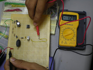
Below are the images of the wirewrapping and the voltage test.


jueves, 2 de octubre de 2008
Database updates
On monday, the staff installed Visual Studio 2008 in all four of our computers. The ODBC driver was also installed in the two remaining computers.
Laura is currently working in the Log In form for officials volunteering in the elections. The form is able to communicate with the database and drop down boxes with information on the db according to selections made in other fields. Laura is currently having issues with displaying some results that are included in three columns.
Angel is currently working with a test application that can prove votes are being inserted into the database. Sylvia has finished designing the UI for the administrator application and is now working with Laura to query information from the database
Functional Inverter and LCD
After receiving the components needed to implement an inverter that was designed for the LCD Screen which is copyrighted in 2006 by Snowleopard Labs and is used in this project by permission with an email for evidence backup.
The inverter has been connected as seen in the following pictures and each node was tested to make sure that the entry voltage did not fluctuate which could cause the LCD's max voltage to be passed causing the LCD to burn out.
The original design was modified to include voltage regulators to add an additional protective measure to avoid any components from receiving more voltage that desired. The voltage input for the inverter was set at 5 volts and the regulator prevents any voltage above this voltage from passing on into the inverter.
Javier was able to successfully complete the circuit and connect it to the LCD which turned on showing lines. At first it was assumed that the lines were not normal, but having done research before implementing the circuit, the lines that appear randomly are normal until the LCD is initialized with firmware.
It is being considered if we are to wire wrap the components and then proceed to the programming of the LCD using the IAR workbence program.

Inverter Connected to LCD

LCD with random lines - The contrast was adjusted using a potentiometer

Inverter Circuit that provides the Backplane voltage for the LCD (Vo)
Suscribirse a:
Entradas (Atom)